Intended Market: Miami DERM
Satisfies Miami DERM 99% efficiency requirements. Learn more about our solutions for this region. Also approved in jurisdictions where a baffle is required.
Satisfies Miami DERM 99% efficiency requirements. Learn more about our solutions for this region. Also approved in jurisdictions where a baffle is required.

99% efficient, 75 GPM grease interceptor
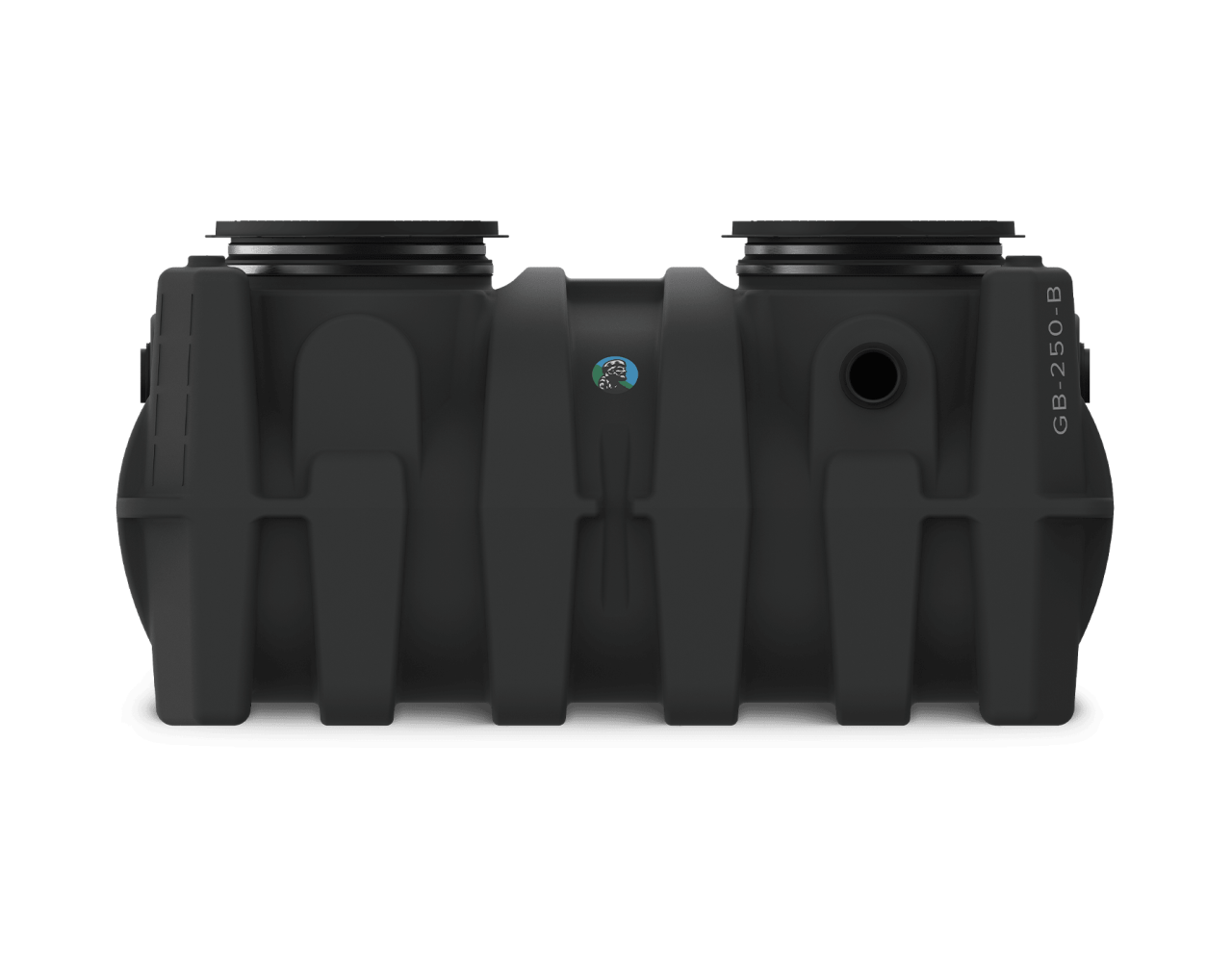
The lifetime guaranteed GB-250-B offers best-in-class certified grease capacity. It is rotationally molded from high density polyethylene with deep structural contours to handle any installation scenario: above grade, buried, indoor or outdoor. Use the Fast Pitch (see FP24) riser system to bring covers to finish grade with speed and precision. The triple outlet feature allows for installation flexibility, including the ability to connect an unused outlet for remote pumpout (see PP3 - this unit requires quantity of 1).
More features:
Hydromechanical performance, third-party certified
No flow control required, certified to Type D of the ASME standard
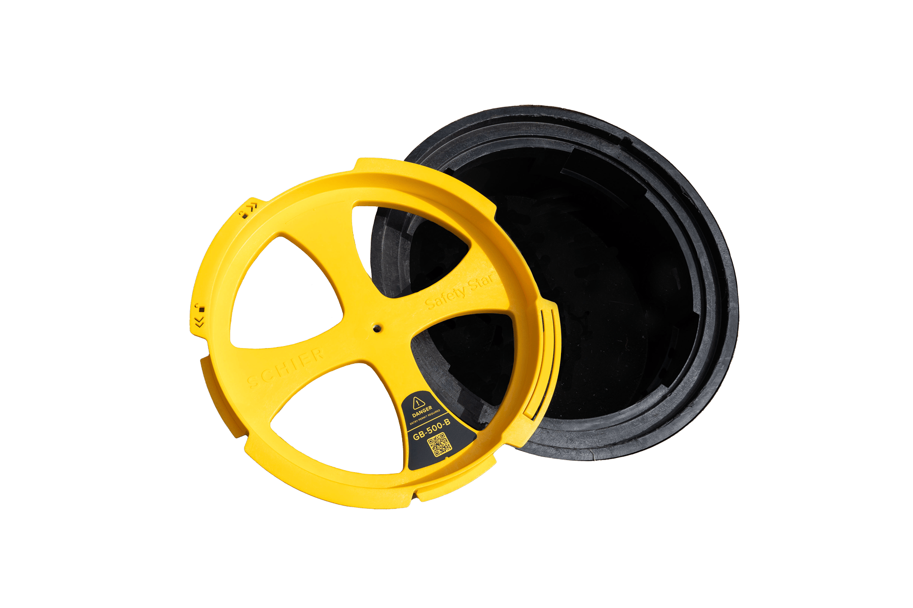
Safety Star® access restrictor prevents accidental entry
Fits through 36" doorways
Sold with temporary cover to be replaced post-install with finish cover
Contains a barrel-style baffle
GB-250 — 100/200 GPM, 277-gallon grease interceptor
Flow Rate/Grease Capacity
75 GPM / 1,560 lbs at 99%
Solids Capacity 55 gal
Liquid Capacity 277 gal
Weight 250 lbs
Installation Location Indoor/Outdoor

Cover adapters can be raised or lowered 2 ½". Adapter trimming may be required for this model when lowering. See installation guide for details.
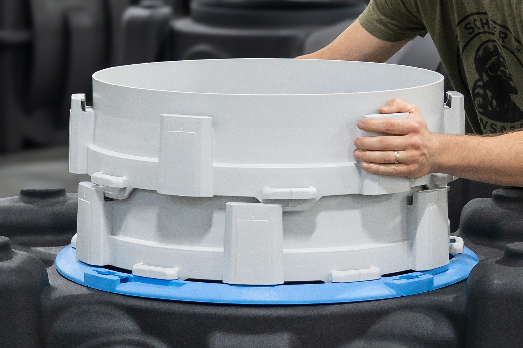
With our easy-to-use, stackable riser system, your buried tank installation will go faster than ever. No cutting, no tools – just stack, twist, lock and repeat.

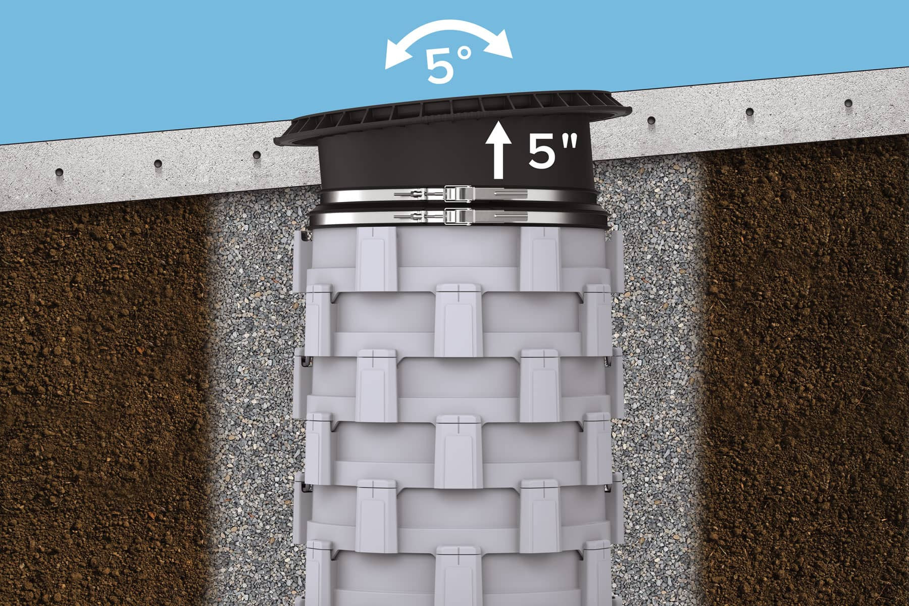
Once your Fast Pitch risers are set, insert and adjust your cover adapter up to 5” or tilt 5 degrees in any direction to achieve any burial dimension and a perfectly flush-with-grade finish cover.

Safety Star has been redesigned to meet the standards of our new Fast Pitch riser system. It includes better structure, a molded-in center nut to fasten the temporary and pedestrian covers, locking ramp and tank product identification.


The Great Basin® line was redesigned and launched in July 2025. To find information on the previous version of this model, visit our "Legacy" page.

Water, grease and solids enter a grease interceptor through an inlet diffuser moving toward the bottom of the tank. The mixture first meets the diffuser foot, which increases cross sectional area and slows the velocity of flow entering the tank. The mixture hits the inlet wall, forcing water and grease to flow upward creating a floating grease layer, while solids sink and settle in the bottom. The dissipation aids in the creation of laminar flow, allowing time for grease and water to separate as they move across the tank. The outlet diffuser draws clean water from the bottom of the tank and delivers it into the downstream flow.
These units are traffic rated if they are installed in accordance with our installation instructions. The unit will need the T24-GI H-20 load-rated cast iron covers and a traffic-rated pad at grade per our installation detail.
No, corrugated pipe is not compatible with Great Basin® indoor/outdoor units. The available riser option is FP24 Fast Pitch® riser. Installing a corrugated pipe riser with this version of the Great Basin® units is not covered by the warranty.
These units have solids capacity of 20% or more of the unit's liquid volume, but food waste grinders can quickly overwhelm a grease interceptor. If the food waste grinder is connected to the unit, we recommend a Billy Goat® solids interceptor in front of the grease interceptor.
All Great Basin® indoor/outdoor models can be installed above grade. The standoffs (4), which are provided standard, ensure the cover adapter(s) do not become unseated in the event of a downstream backup. A GB-500 installed above grade must also have the above grade support kit (AGS2).
These units can be used with a dishwasher. If the dishwasher will have a discharge temperature higher than 150 degrees Fahrenheit, the system will require a drain tempering valve to reduce the water temperature.
Yes, these units can be suspended with cover adapter(s) penetrating the floor above (with the exception of GB-1000 and GB-1500). The unit needs to be fully supported across the bottom with risers extending to the floor above. It is the responsibility of the specifying engineer or installer to design a support system appropriate for the weight of the unit with water. If suspending a GB-250, the unit must be installed with the above grade support kit (AGS1). If suspending a GB-500, the unit must be installed with the above grade support kit (AGS2).
If the units will be installed in an area where the water table will crest the top of the tank shoulders, additional steps need to be taken to protect the unit from the extreme hydrostatic forces. The unit would need to be placed in a water tight vault or encased in concrete. If there is a possibility that ground water will come into contact with the unit, there needs to be a high-water/anti-flotation anchor kit installed (AK1, AK2, AK3).
These units do not require a fixture vent. The internal design of the unit will ensure proper function without a fixture vent. Any venting to the piping connected to our unit is at the discretion of the local authority.
There should be a minimum of 6" between the units when installed in series. In a buried application, this space will ensure there is enough backfill in between the units.
If you're looking for legacy products, please visit the Legacy Products page
Due to the low head pressure in this scenario, the first solution is to remove the internal flow control (applies only to Type C certified units with red flow control cartridge). This flow control cartridge is provided to ensure the maximum flow rate in GPM is not exceeded in basement applications, as the unit was certified to the ASME standard and not necessary in low flow applications. If that doesn’t solve the issue, the next solution is to add a flow restrictor to the tailpiece of the fixture. Contact support@schierproducts.com for more information.
The adjustable cover adapters that ship with these units offer up to 5" of built-in riser height. When more is needed, each Fast Pitch® riser section provides an additional 5" in height. Use our resources here to calculate how many risers you need based on either the distance from the top of the buried tank or the centerline of the buried tank.